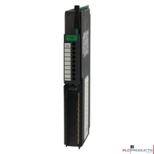
Allen-Bradley 1771-OB
You can directly drive terminals on a DC (12-24V) Input Module (cat. no. 1771-IB) from terminals on the DC (12-24V) Output module (cat. no. 1771-OB) as shown in Important: Use the same dc power source to power both modules to ensure that ground is at the same potential.
The front panel of your module contains 9 red status LED indicators. The top LED is the fuse blown indicator. It illuminates when a fuse has blown in the module. The remaining 8 red status indicators correspond to each of the 8 inputs. They illuminate when the corresponding output energizes.
Each of the 8 outputs on the module are individually fused to protect the user's power supply. Fuses are accessed by removing the front component-side cover on the module.
Outputs per Module: 8
Module Location: 1771 I/O chassis
Input Voltage Range: 10 to 27V dc
Output Current: 1.5A per output (not to exceed 8A per module)
Surge Current (maximum): 4A for 1ms, repeatable every 1 second
Off-state Leakage: Current 1mA per output
On-state Voltage: Drop 2V dc (maximum)
Delay Times Turn on/off: 10ms
Power Dissipation: 16.9 Watts (max.), 0.9 Watts (min.)
Thermal Dissipation: 57.6 BTU/hr (max.), 3.0 BTU/hr (min.)
Backplane Current: 165mA @ 5V dc +5%
Opto-electrical: Isolation 1500V ac (RMS)
Connections to the output driver module are made to the 10 terminal field wiring arm (cat. no. 1771-WA) shipped with the module. The wiring arm pivots on the I/O chassis to connect with the terminals on the front of the module. The wiring arm allows the module to be removed from the chassis without disconnecting the wiring.
|
Category |
Models |
|---|---|
| Cable | Allen-Bradley 1771-CP1 |
| Encoder | Allen-Bradley 1771-HTE |
| Power Supplies | Allen-Bradley 1771-P2, Allen-Bradley 1771-P4S, Allen-Bradley 1772-P1 |
| Standard Power Supplies | Allen-Bradley 1771-P7, Allen-Bradley 1771-PA |
| Teach Pendant Interface | Allen-Bradley 1771-HD |
cab-bat-pow-acc
Cables, batteries, power supplies and other accessories are sold separately unless otherwise stated.


