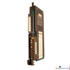
Allen-Bradley 1771-OGC
The TTL module requires power from two sources: the I/O chassis backplane, and a +5V dc power supply that you provide for transmission of TTL signals.
The TTL module receives its power through the 1771 I/O chassis backplane from the chassis power supply. The module requires 168mA from the output of this supply. Add this to the requirements of all other modules in the I/O chassis to prevent overloading the chassis backplane and/or backplane power supply.
You must provide a separate +5(+0.25)V dc power supply for TTL outputs from the module and for your TTL input devices. Your module requires 250mA from the output of your supply. Ripple should not exceed 50mV peak to peak.
The module circuit board is slotted in two places on the rear edge. The position of the keying bands on the backplane connector must correspond to these slots to allow insertion of the module. You can key any connector in an I/O chassis to receive this module except for the left-most connector reserved for adapter or processor modules. Place the keying bands between the following numbers labeled on the upper backplane connector:
Between 6 and 8
Between 10 and 12
The standard voltage levels required for the DL20 parallel port are 5 to 30 VDC. When using DC Output Modules, an external power supply of the appropriate voltage level and current capacity is required.
|
Category |
Models |
|---|---|
| Cable | Allen-Bradley 1771-CP1 |
| Encoder | Allen-Bradley 1771-HTE |
| Power Supplies | Allen-Bradley 1771-P2, Allen-Bradley 1771-P4S, Allen-Bradley 1772-P1 |
| Standard Power Supplies | Allen-Bradley 1771-P7, Allen-Bradley 1771-PA |
| Teach Pendant Interface | Allen-Bradley 1771-HD |
cab-bat-pow-acc
Cables, batteries, power supplies and other accessories are sold separately unless otherwise stated.


