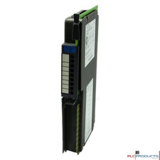
Allen-Bradley 1771-IQ
MSRP:
Price:
Warranty:
Guarantee:
Category:
Series:
Reference:
The Allen-Bradley 1771-IQ DC Selectable Input Module accepts DC (5-30V) voltage levels on all 8 inputs and converts these signals to logic levels. Each input circuit is individually selectable for current source (current flowing from the 1771-IQ to the DC input device) or current sink capability (current flowing from the DC input device to the 1771-IQ). This module may also be configured from either HIGH TRUE or LOW TRUE logic with an input delay of 1ms maximum or 12ms typical. For the HIGH TRUE setting, TRUE is any voltage greater than 40% of the external supply voltage, and LOW is any voltage less than 20% of the external supply voltage. For the LOW TRUE setting, HIGH is any voltage less than 20% of the external supply voltage, and LOW is any voltage greater than 40% of the external supply voltage. The nominal input current per channel for an ON condition is 5mA for 5V DC, and 25mA for 30V DC. The external supply voltage power supply must be able to provide 100mA per module at 5V DC, and 350mA per module at 30V DC.
Power Requirements
The Allen-Bradley 1771-IQ Contact Output Module may be installed in any Allen-Bradley Universal I/O Chassis, 1771-A1B, 1771-A2B, 1771-A3B, or 1771-A4B. Before Installation, calculate the power requirements of the modules currently in the chassis. Add to that 150mA @ 5V DC, the current required by the 1771-IQ. Check to be sure that this combined current requirement does not exceed the current driving ability of the chassis power supply.
Module Location in the I/O Chassis
The 1771-IQ may be place in any slot of the I/O chassis with the exception of of the extreme left slot. This slot is occupied by the Remote I/O Adapter Module. It is suggested that analog input modules and low voltage DC modules be placed away from AC modules or high voltage DC modules to minimize electrical noise interference.
1771-IQ DC Selectable Input Module Use
The front panel of the 1771-IQ contains eight red status indicators. Each of these indicators corresponds to a single circuit within the module. When the input to a specific circuit is TRUE (whether the module is selected for HIGH TRUE or LOW TRUE logic), its corresponding status indicator will illuminate. The top LED will indicate the status of signal 0, while the bottom LED will indicate the status of signal 7.
Number of Inputs: 8
Voltage Category: Sink or Source Load
Operating Voltage: 5-30V
Backplane Current Load:150 mA
Applications:Source or sink input signal termination time-critical applications
|
Category |
Models |
|---|---|
| Cable | Allen-Bradley 1771-CP1 |
| Encoder | Allen-Bradley 1771-HTE |
| PLC | Allen-Bradley 1777-P2 |
| Power Supplies | Allen-Bradley 1771-P2, Allen-Bradley 1771-P4S, Allen-Bradley 1772-P1 |
| Standard Power Supplies | Allen-Bradley 1771-P7, Allen-Bradley 1771-PA |
| Teach Pendant Interface | Allen-Bradley 1771-HD |
| w/ Power Supply Racks/Chassis | Allen-Bradley 1772-LP3-RACK+PS |
cab-bat-pow-acc
Cables, batteries, power supplies and other accessories are sold separately unless otherwise stated.


